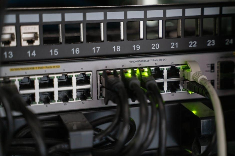
The Generac Manual Transfer Switch Wiring Diagram is a comprehensive guide for safely connecting portable generators to electrical systems, ensuring reliable power transfer and preventing electrical feedback issues․

1․1 Overview of Generac Transfer Switches
Generac transfer switches are designed to operate independently with standard generators using a 2-wire start mechanism․ The TX range includes models with integrated displays and touchpads for local programming․ These switches are controlled by advanced controllers that manage transfer operations, generator functions, and setpoint timing․ They are compatible with various generator models, ensuring seamless power transition between utility and generator sources․ The switches are built to meet safety standards and regulatory requirements, providing reliable performance during power outages․ Installation guides and wiring diagrams are provided for proper setup, emphasizing the need for professional electrical expertise to ensure safety and compliance with local codes․
1․2 Importance of Proper Wiring Diagrams
Proper wiring diagrams are essential for ensuring safe and effective installation of Generac transfer switches․ They provide a clear visual representation of connections, helping to prevent electrical hazards and guarantee compliance with safety standards․ Incorrect wiring can lead to dangerous conditions such as electrical feedback, fire risks, or system malfunctions․ Generac manuals include detailed wiring schematics to guide installers through the process, emphasizing the need for precise connections between generators, transfer switches, and electrical panels․ Adhering to these diagrams ensures reliable power transfer, protects equipment, and avoids potential legal or safety issues․ Professional electricians rely on these diagrams to meet local electrical codes and regulations, ensuring long-term system reliability and safety․

Safety Guidelines for Installation
Always disconnect power sources before starting installation to prevent electric shock or injury․ Follow manufacturer instructions and local electrical codes to ensure a safe and reliable setup․

2․1 Precautions Before Starting the Installation
Before installing a Generac manual transfer switch, ensure all power sources are disconnected to avoid electrical shocks or injuries․ Always wear protective gear, including gloves and safety glasses․
Read the entire manual thoroughly to understand the installation process and safety protocols․ Verify that the generator and transfer switch are compatible with your electrical system․
Ensure the area is well-ventilated and free from flammable materials․ Double-check that the generator is turned off and the electrical panel is de-energized before proceeding․
Never attempt installation without proper knowledge of electrical systems․ If unsure, consult a licensed electrician to ensure compliance with local electrical codes and regulations․

2․2 Understanding Electrical Codes and Regulations
Understanding electrical codes and regulations is crucial for a safe and compliant installation of a Generac manual transfer switch․ Ensure all work adheres to the National Electric Code (NEC) standards and local electrical regulations․
Verify that the transfer switch is properly rated for your system’s voltage and current requirements․ Always use approved wiring materials and connections to prevent fire hazards and ensure reliable performance․
Local authorities may require inspections to confirm compliance with electrical codes․ Familiarize yourself with permits and certifications needed before starting the installation process․
Adhering to these guidelines ensures the system operates safely and efficiently, protecting both people and property from potential electrical risks․
Understanding the Generac Manual Transfer Switch Wiring Diagram
The Generac manual transfer switch wiring diagram provides a clear guide for connecting utility and generator power sources to essential circuits, ensuring safe and proper installation practices․
3․1 Key Components of the Wiring Diagram
The key components of the Generac manual transfer switch wiring diagram include the utility power source, generator power source, transfer switch, and circuit connections․ The utility power line connects to the electrical panel, while the generator line links to the transfer switch․ The transfer switch acts as the central control, directing power between utility and generator sources․ Clear labels and symbols indicate live wires, neutral connections, and grounding points․ The diagram also highlights circuit breakers, fuses, and load centers, ensuring proper electrical flow and safety․ Understanding these components is essential for accurate installation and operation, ensuring reliable power transfer during outages․
3․2 How to Read and Interpret the Diagram
To read and interpret the Generac manual transfer switch wiring diagram, start by identifying the key symbols and labels․ These represent components like the utility power source, generator, transfer switch, and circuit connections․ Lines in the diagram indicate wires, with colors often signifying different power sources or phases․ Begin by tracing the utility power line to the transfer switch, then follow the generator connection․ Understand the flow of electricity between the utility and generator sources․ Note the circuit breakers, fuses, and load centers, as they ensure safe power distribution․ Pay attention to grounding points and neutral connections for proper electrical safety․ By systematically analyzing each section, you can accurately connect and configure the transfer switch for reliable operation․
Installation Steps for Generac Manual Transfer Switch
Mounting the transfer switch, connecting the generator, and linking to the electrical panel are essential steps․ Ensure compliance with safety guidelines and electrical codes for proper installation․
4․1 Mounting the Transfer Switch
MOUNTING THE TRANSFER SWITCH IS A CRITICAL STEP IN THE INSTALLATION PROCESS․ First, identify a suitable location for the switch, ensuring it is indoors, near the main electrical panel, and protected from moisture and extreme temperatures․ Use the provided mounting hardware to secure the enclosure to the wall, ensuring it is plumb and level․ Connect the generator and electrical panel wires to the switch, following the wiring diagram․ Proper alignment and tightening of connections are essential to avoid electrical issues․ Finally, double-check the installation for compliance with local electrical codes and the manufacturer’s guidelines․ Improper mounting can lead to safety hazards and system malfunctions, so precision is key․ Always refer to the manual for specific mounting instructions and torque specifications․
4․2 Connecting the Generator to the Transfer Switch
CONNECTING THE GENERATOR TO THE TRANSFER SWITCH REQUIRES PRECISION AND CARE․ Begin by ensuring the generator is turned off and disconnected from any power source․ Locate the appropriate terminals on both the generator and the transfer switch, referencing the wiring diagram for accuracy․ Use the correct gauge wire to connect the generator’s output terminals to the transfer switch’s input terminals․ Ensure all connections are secure and tightened properly to avoid loose wires, which can cause electrical issues․ Double-check the polarity to prevent damage or malfunction․ Finally, turn on the generator and test the connection to ensure power is transferred smoothly to the transfer switch․ Always follow the manufacturer’s guidelines for specific wiring configurations and safety protocols to avoid hazards․ Proper connections are essential for reliable operation and safety․
4․3 Connecting the Transfer Switch to the Electrical Panel
CONNECTING THE TRANSFER SWITCH TO THE ELECTRICAL PANEL IS A CRITICAL STEP IN THE INSTALLATION PROCESS․ Begin by identifying the correct terminals on the transfer switch that correspond to the electrical panel․ Use the wiring diagram to ensure proper connections, as incorrect wiring can lead to system malfunctions or safety hazards․ Connect the load terminals on the transfer switch to the appropriate circuits in the electrical panel, ensuring all wires are securely fastened․ Double-check the wire gauge to match the system’s requirements, as specified in the manual․ Once connected, verify that the transfer switch is properly configured to prioritize power sources, ensuring seamless switching between utility and generator power․ Finally, test the system to confirm that power is distributed correctly to all connected circuits․ Always adhere to local electrical codes and safety guidelines when making these connections․

Troubleshooting Common Wiring Issues
Identify issues like loose connections, incorrect wire sizing, or improper grounding․ Verify all terminals match the wiring diagram․ Test circuits to ensure proper power flow and safety․
5․1 Identifying and Resolving Electrical Connectivity Problems
Identifying electrical connectivity issues in a Generac manual transfer switch involves checking for loose connections, damaged wires, or incorrect terminal placements․ Start by reviewing the wiring diagram to ensure all connections match the manufacturer’s specifications; Use a multimeter to test for continuity and voltage drops․ If a wire is loose, tighten it securely․ For damaged wires, replace them with appropriately sized cables․ Ensure all terminals are properly grounded to prevent electrical hazards․ Refer to the installation manual for specific troubleshooting steps․ Addressing these problems promptly ensures reliable power transfer and system safety․ Always follow safety guidelines to avoid electrical shocks or system malfunctions․
5․2 Common Mistakes to Avoid During Installation
Common mistakes during Generac manual transfer switch installation include improper grounding, reversed polarity, or incorrect wire sizing․ Ensure all connections strictly follow the wiring diagram to avoid electrical hazards․ Never skip the grounding process, as it is critical for safety․ Avoid using damaged or undersized wires, as this can lead to overheating or system failure․ Always disconnect power sources before starting work to prevent electrical shocks․ Incorrect terminal connections can cause malfunction or damage to the switch․ Double-check all connections before powering up the system․ Additionally, never bypass safety features or ignore local electrical codes․ Adhering to the installation manual and seeking professional help if unsure ensures a safe and reliable setup․

Maintenance and Upkeep of the Transfer Switch
Regular inspections, cleaning, and testing ensure optimal performance․ Replace worn parts promptly and follow manufacturer guidelines for long-term reliability and safety․ Schedule periodic professional checkups․
6․1 Regular Inspections and Testing
Regular inspections are crucial for ensuring the transfer switch operates safely and efficiently․ Start by visually examining all connections and wires for signs of wear or damage․ Verify that all terminals are securely tightened and free from corrosion․ Perform a functional test by simulating a power outage to ensure the switch transfers power correctly․ Use a multimeter to check for any voltage drops or electrical faults․ Additionally, test the automatic features, if equipped, to confirm they activate as intended․ Document each inspection and test result for future reference and maintenance planning․ Regular testing helps identify potential issues before they escalate․
6․2 Best Practices for Long-Term Reliability
To ensure long-term reliability, adhere to best practices for maintaining the Generac manual transfer switch․ Schedule annual professional inspections to verify compliance with safety standards and electrical codes․ Keep the switch clean and dry, as moisture can lead to corrosion and malfunction․ Avoid overloading the system, as this can cause premature wear․ Store backup power cables neatly and protect them from physical damage․ Regularly update software or firmware for smart-enabled switches․ Train users on proper operation procedures to prevent misuse․ By following these practices, the transfer switch will remain a dependable component of your emergency power system, ensuring consistent performance during power outages․